Dilution can be defined as- Contribution of Base Material into weld metal (e.g. Base Materials + Filler Metal):
So, looking at the picture, for autogenous mode (without filler material addition), for same base material, Total dilution =100%.
Means, the total contribution of the same base metal into weld metal is 100 %, While for Non-autogenous mode (with Filler material addition), dilution % depends on many factors such as:-
Selected Joint design & welding Processes
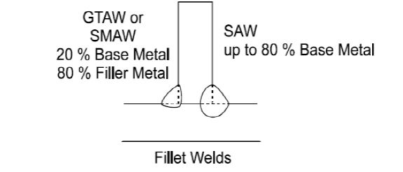
As can be seen in figures below, usually with SMAW, GMAW & GTAW processes, 15-20% of the contribution from base metal (i.e total 20 -40 %, from each side of the joint) is expected. While in SAW process, due to its high arc efficiency as much as 80% contribution from base metal is expected.
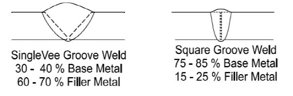
Groove geometry is also playing an important role as shown in self-explanatory schematics below:-
Heat Input
Hnet (KJ/mm) = V X I X 60 / S X 1000
Where, V=voltage, I=Amperage, Travelling speed (S) in mm/min
Higher H.I. can lead to more dilution. If you are joining CS/LAS to SS 304L or 316L using ER309L. You should be more careful to control H.I Since, higher H.I can lead more carbon dilution from CS/LAS side into weld metal resulting in weld solidification cracking due to primary austenite solidification mode only.
However, ER 309L is designed to retain some ferrite in as weld solidified structure to prevent the solidification cracking in the weld joint.
In a fusion Welding process depending on electrode/filler used or not, if used, depending upon matching chemistry of the electrode/filler material with base metal decide the type of solidification-
For example, if no Filler material is used,
Autogenous–No filler material
Homogeneous–Filler metal chemistry similar to the base material
Heterogeneous–Filler metal chemistry is dissimilar to the base material
Let us understand, the dilution rate using the simple example
Assume 430 Ferritic SS base metal is joined with 308 filler, with 35% dilution,
| C | Cr | Ni | Mn | |
| Filler composition | 0.06 | 20.3 | 11.3 | 1.5 |
| Base metal composition | 0.09 | 17.3 | 0.4 | 0.6 |
| Filler X 0.65(1-dilution) | 0.039 | 13.2 | 7.4 | 1.2 |
| + Base X 0.35 (dilution) | 0.032 | 6.11 | 0.1 | 0.2 |
| Weld Metal | 0.071 | 19.3 | 7.5 | 1.4 |
Ref 1:- From lecture notes:-Engineering Materials, Materials Joining and NDT, Aalto University, School of Engineering, Department of Engineering Design and Production.
In weld overlay, filler metal accepts dilution and alloy with base metal chemistry to give crack-free continuous, ductile matrix (crack sensitive free microstructure) weld metal.
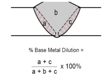
% Dilution = (X / X + Y) X100, Where X= amount of Base Metal Melted. Y= Sum of Base metal + Filler added
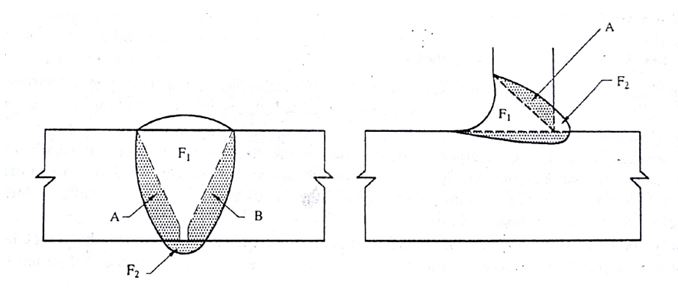
Schematic for estimating dilution by two base metal A & B, when welded with Filler F
Source:- Article on “Dissimilar Metal welding & Cladding”, Dr A K Bhaduri, Welding Technology for Engineers, Narosa Publishing House. New Delhi
DILUTION BY METAL A % = A / A +B + (F1+F2) x100
DILUTION BY METAL B % = B / A +B + (F1+F2) x100
TOTAL DILUTION, % = A + B / A + B + (F1 +F2) X 100
The average percentage of elements in diluted weld metal calculated as per AWS Formula [Ref:- 2 ]:-
Xw = (DA) (XA) + (DB)(XB)+ (1-DT)(XF)
Where, Xw = % of average X Element in Weld metal composition
DA = % Dilution by material A
DB = % Dilution by material B
XA= % of X element in material A
XB= % of X element in material B
DT = % Total dilution of by material A & B, when welding with filler metal F
XF= % of X element in filler F
For example, assume that Type 316 SS Welded to 2.25 Cr-1 Mo, Low alloy ferritic pressure vessel Steel with NiCr filler ERNiCr-3.
| Dilution | Alloy | Cr %wt | Ni %wt | Mo %wt | Fe %wt |
| 15 % | 2.25 Cr-1 Mo | 2.5 | – | 1.0 | 95.5 |
| 20% | 316SS | 17.0 | 12.0 | 2.5 | 63.0 |
| 65 % | ERNiCr-3 | 20.0 | 72.0 | – | 3.0 |
Assuming total dilution 35% (15% by Cr-Mo alloy steel + 20% by 316 SS)
Average % of Cr, Ni & Mo are estimated as under:-
Cr% = 0.15(2.5) + 0.20(17.0)+0.65(20.0)=16.8
Ni%= 0.20(12.0) +0.65(72.0) = 49.2
Mo% = 0.15(1.0)+ 0.20(2.5) = 6.65
Ref 2:- Dissimilar Metals, Welding Handbook, 7th Edn, Vol. 4, AWS, Miami, USA, 1982 pp. 514-547
